HardwareResource
Hardware Features
i2S-6UB series SOM module
CPU: 1x ARM® Cortex®-A7 core, Running frequency up to 800 MHz
RAM: 512MByte 16bit DDR3L
Flash:8bit eMMC Flash, Capacity 4GB
2x 10/100M ethernet ports
Serial Ports
1x RS232 port, wiring terminal
2x RS485 port,Built-in 15KV ESD Protection, Galvanic Isolation, Terminals
2x LEDs indicators are “PWR”, “RUN”
Support WiFi 2.4GHz network, Antenna utilizes standard SMA connector (male and female threads)
Support 4G network, Standard SMA connector for the antenna (male and female threads), Micro SIM card slot
Supports 4G Cat1 or Cat4 rates
Antenna specifications: suction cup antenna, gain 5dBi, internal needle
Antenna size: height 317mm, suction cup diameter 30mm, feed line length 100cm
frequency band of an antenna: 698~960Mhz,1710~2700Mhz
Support LoRaWAN network, antenna with standard SMA antenna connector (female thread on female hole)
LoRaWAN470, frequency range 470 ~ 510MHz
LoRaWAN868, frequency range 863 ~ 870MHz
LoRaWAN915, frequency range 902 ~ 928MHz
Supports DC 9 ~ 24V wide voltage inputs
Supports one USB Host interface
built-in RTC chip
Built-in external watchdog design to ensure system stability
PCB Size (W x L x H) : 53 x 140 x 119.5mm
Industrial temperature range(-40°C - 85°C), WiFi modules are commercial grade
4G Cat1 supported bands
China Mainland CN:
- LTE FDD, B1, B3, B5, B8
- LTE TDD, B34, B38, B39, B40, B41
European Region EU:
- LTE FDD, B1, B3, B5, B7, B8, B20, B28
- LTE TDD, B38, B40, B41
Hardware block diagram
Functional diagram
GW102 gateway use our i2S-6UB SOM module for design, with rich peripheral interfaces and internal resources. The functional block diagram is as follows:
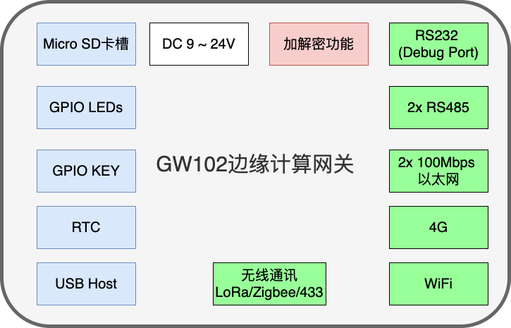
Functional Block Diagram Description
The green box is the communication interface
Red boxes are optional features
Interface Description
Physical drawing of the front interface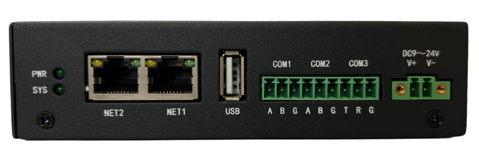
Physical drawing of the left side interface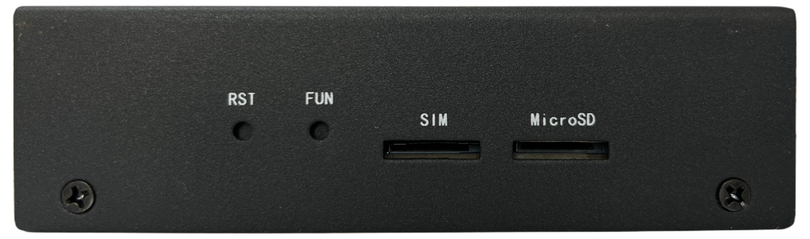
Physical drawing of the right facia interface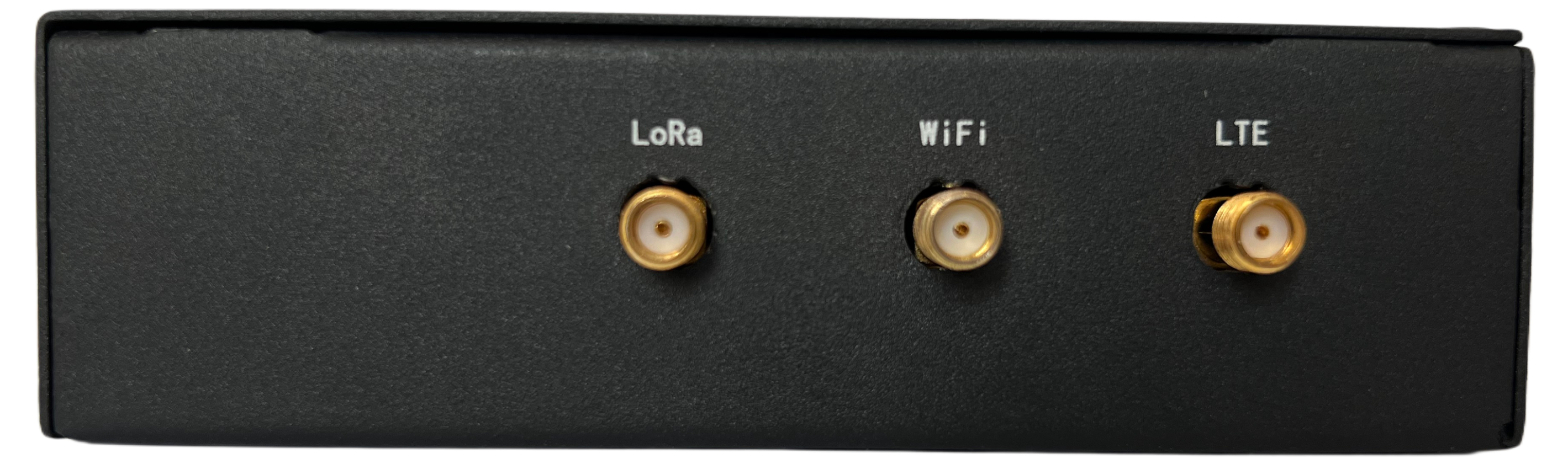
Interface function
| Interface | Description |
|---|---|
| Power | DC 9 ~ 24V |
| LED Indicators | Two indicator lights, one power indicator and one system operation status light |
| Ethernet | 2x 10/100Mbps Ethernet, Standard RJ45 connector |
| USB Host | 1x USB 2.0 Host Type-A connector |
| Serial Port | 1x RS232 serial port, 2x RS485 serial port |
| LoRa Antenna Interface | SMA connector |
| WiFi Antenna Interface | SMA connector |
| 4G Antenna Interface | SMA connector |
| Boot device jumper | Optional system boot from different devices, supports NAND Flash, eMMC Flash and SDCard |
| GPIO KEY | Developer customizable features |
| Micro SD | 1x Micro SD slot |
| SIM slot | 1x Micro SIM slot |
| TTL debug port | Inside the PCB for Linux system debugging and maintenance management functions |
Power supply parameters
Standard Power Supply: DC 12V/1.5A
Supported power supply range: DC 9~24V
Power consumption performance
| test item | Average power consumption | clarification |
|---|---|---|
| Wireless turned off, system on standby | 12V/95mA | disable 4G,LoRaWAN and WiFi function |
| Wireless enabled, system standby | 12V/200mA | enable 4G,LoRaWAN and WiFi function |
| System standby with only 4G enabled | 12V/110mA | disable LoRaWAN and WiFi function. enable 4G function |
Physical property
Housing: Metal housing
Overall dimensions:136 x122 x 35 mm (Antennas and mountings not included)
Weight:About 722g (No antenna installed)
Working Temperature: -40 ~ +85ºC
relative humidity:95%(non-condensing)
最后编辑:SteveChen 更新时间:2025-04-23 00:55